Friday, May 7, 2010

2010 Digifab Assembly Rodeo

Final Assignment challenged students to design and digitally fabricate an architectural prototype which would be assembled by a third party. Students provided a set of instructions to be used by the assembler. Enjoy the results!

Wednesday, May 5, 2010

Digitally Fabricated Coffee Table

Digitally Fabricated Coffee Table
By Brian Akert and Jared Carda
We decided to design and build a coffee table for our digital fabrication class that would be manufactured by our college's CNC machine. We began our design process by figuring out how we can cut our simple sections in order to create an overall form that cantilevers to a small point opposite of a heavy mass that makes up the bulk of the table.
Using Rhino3D, we came up with a form that would be easily contoured and extruded into the "ribs" of the structure. These would be held together by a ring that surrounds a custom piece of plate glass supplied by a third party. The counterweight for the cantilevered form would consist of a concrete shelf that would be able to both balance the piece and keep rigidity throughout the structure.
We set up our CNC cuts through RhinoCAM so that the pieces would fit tightly within each other. Each of these connections were measured with exact tolerances as to make sure the piece would be able to be held together by friction alone. However, just to be safe, we added a very small amount of glue to each joint.
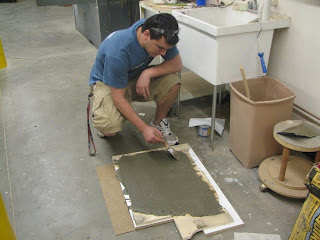
Our concrete form was cut out by the CNC machine and then was filled with concrete and fiberglass and left to dry overnight.
The assembly process is shown in the pictures below:
Digital Design


Writing the G-Code in RhinoCAM


CNC Machine


Construction


Concrete Form


Finished Product


Tuesday, April 27, 2010

Double Curved Surface Assignment


Sara A. Ben Lashihar


This double curved surface was produced by using Paneling Tooling plug-in in Rhino 4.0 with volume (30 cm X 30 cm X 3 cm).

The mold was produced by CNC machine with foam material. Parallel finishing was used directly in engraving the material because foam is soft and fast cutting and this technique will not harm the cutting tool.


Concrete material was used to create the opposite mold. The first attempt was failed because of the thin thickness of the concrete block.

In the second try, the thickness was increased to about 3.5 cm to avoid the breaking. Before pouring the concrete mixture on the foam mold, I used Petroleum jelly to facilitate the process of separating the concrete block from the foam.


Monday, April 5, 2010

Developable Boxes


Sara A. Ben Lashihar

The first idea is based on the integration between 4 forms of leaves and create a complex model linking these forms.
The second idea is simple and based on linking between two parts of cylinders.


Thursday, March 11, 2010

Skin and Bones Paneling

As we began the skin and bones design project. We had the goal of each creating a model that dealt with each persons thesis project. This would give us each a model that would be a section of our individual thesis. Each of us has a different lattice structure that is unique to our project. The goals was the create three different examples of our structures and how we used skin with the structure.

In the first iteration, the bones were required to be extremely small in scale to allow it to read as a doubly curved surface and ultimately could have resulted in the failing of the project. It had printed but because the 3d printer had malfunctioned in saying the glue was full and it was actually empty it did not print. Due to the time sharing amongst our own group and other groups we decided to work with the other two iterations of the group.

Idea: The idea behind the surface was to create a paneling system for exploration. This frame would be able to accept any panel as long as it could relate to the different dimensions that the system presents. Those shapes area a four sided polygon and a six sided polygon. The angles and actual dimensions differ from every panel. This allows for situational experimentation.



The second iteration, consisted of an organic structural frame that had round openings in it. The idea behind this skin and bones design is that the bones are on the exterior, bringing the skin to the inside. It becomes an exoskeleton sort of structure. The module unit is designed as a prefabricated piece that connects itself to the larger frame. In a way, when all the modules are connected to the frame, the modules then become the skin. The frame was created as a bone structure. The module would have a glass frame skin that is on the inside of the shell, although that part of the project has not been produced yet.


For the third and final skin and bone exploration, Ashley explored a lightweight space frame that would hold up an ETFE double-curved panel surface. The base surface and grid system for this project was created by lofting two shifted arcs. From that surface, using the paneling tools in Rhino, she created a grid from surface UV. From this grid and surface, two panel systems were created.


The first system was a diagonal panel system. The diagonal panel system was offset in relation from the original surface, 1". Between these two panel systems, a voronoi pipe script was used to create a space-frame structure. This structure was capped to create a solid form. To prep this model for the 3D Printer, we exported the space frame model as an .stl and loaded in into the 3D printer's software, ZPrint.


The second panel system was created from the original lofted surface. This surface was paneled using a flat-face, box pattern through the Rhino Paneling tools. After creating the flat panels from the surface, we unrolled the panels to create a laser cutter template file. In order to keep the panels in order, we labeled the panels according to which row and column there were in. On the laser cutter, we used two vector settings; one for cutting the panels out and one for labeling them. Our cut setting was: power 3%, speed 10, and ppi 300. Our vector setting was: power 1%, speed 15, and ppi 300. We ran of these cut paths twice to reduce melting the plastic.


After completion of the printing process we had to begin the post processing phase. The laser cutting had left a burnt rusty look on the edges of the plexiglass which we decided to try to cover. The clear plexiglass was also not looking like we wanted because it did not show up well when it was clear transparency. We decided to frost the plexiglass to create a frosted look blurring the transparency. This gave a better look to the skin and also helped to cover the burnt edges a bit as well.

To attach the skin we had to tack glue it to the frame. This was the only option we had because we did not design a system to connect the two together before hand. The pieces were individually numbered so that we were able tell which pieces needed to go where. This made the connection process go fairly quick. We did not design the skin for any tolerance, using only the width of the laser cut as the tolerance. The pieces were able to fit together and curve along the frame when it was all completed giving a look of frosted glass with a space frame system behind it. The translucency of the skin created a abstraction which enhanced the look of the skin and bones design.


Skin & Bone Exercise
Jon Martin
Jason Wheeler

original shape
skin and bone assembly
grasshopper production
We used the shape of a distorted torus to explore our skin
and bone study. Using Grasshopper, we were able to rib the
shape and lay out pieces for laser cutting. The process of
ribbing a 3d shape (especially one with a hole in it) as
opposed to a surface, proved to have many unexpected
challenges, such as assembly process.
We used 1/8" hardboard for the ribs. All the pieces fit on
three 18"x32" sheets

Laser Settings were:
Pass1 - power: 100; Speed : 10; PPI: 250
Pass2 - power: 100; Speed : 10; PPI: 250
Pass3 - power: 75; Speed : 12; PPI: 250

We gave a material thickness of .110" in grasshopper to
account for space made by the laser thickness. This was to
make it so the pieces fit together tightly, to eliminate gluing
(Not a good idea!) The tight fit made the pieces almost
impossible to fit together, so a little slack might have made
our assembly process a bit easier.
We used the cnc to fabricate the external shell pieces for
the torus out of a piece of rigid insulation. The big
experiment here was trying to flip the foam over once one
side was milled and continue milling the backside. This would
give us thin layers of foam that we would cut out with a
knife and coat with fiberglass.

The cnc took 9 hours total. We started with a 1/2" rough
cut with 50% stepover and finished with a 1/4" parallel finish
with 20% stepover. In the process of flipping to the
backside we realized the x-direction was off by 1". To fix
this we re-oriented the origin to -1" from where it was. Our
thought process was to mark the outline of the board with
marker so that when it was flipped it would sit in the same
spot, but something is wrong with that process (probably in
setting the origin.)

The most tedious process probably comes with finishing and
coating the shell pieces. We didn't anticipate the problems we
would encounter with resin's eating away at the foam. Our plan
was to fiber glass over the panels, Bondo and spot finish, then
coat with a glossy car paint. Our first test piece wound up
looking more like a skin graft than any type of sleek sexy panel.
To fix this we had to apply several layers of WeldBond (a kind of
tacky glue) to make a watertight seal over the foam. From there
we could apply the fiberglass resin in multiple layers and finish
with lots of sanding. Foam still proved to be too brittle and weak
to attain any kind of flawless surface.