Wednesday, March 10, 2010


Kyle Miller and Kory Randa worked collaboratively to bring you the most awesome skin and bones project ever created in the history of man. No mere mortal words can ever be written to fully justify the greatness of this project, so we shall let the images of greatness be evidence for our work and skill. Do not be afraid to bask in the glory of our presence.
...but just to sum it up we created a seat surface in rhino and exported contours of it to cad where the frame was drawn, then we CNCed the living daylights out of it, and created a mold of the seat surface. Then we used the mold to create a fiber glass resin seat that we painted and sanded, and put clippy things on the bottom to hold it in place ... so thats our chair.

Honey Comb Structure


Skin & Bones Assignment

Honey Comb Structure

Sara A.Ben Lashihar

The idea of this project is simple and based on the concept of creating a double surface structure consisting of several honey combs as a basic unit for the model. The structure was created by 3Dprinter, while the skin was made of wood by CNC machine and be placed on the structure.


Skin and Bones


Our 4th assignment concentrated on using a structural frame system (bones) to hold up a cladding system (skin). We first started by making a simple surface in Rhino and extruded a frame out of an overlayed grid. The frame was laser cut from a 2-dimensional CAD file and assembled by hand. We then took the same shape into grasshopper and divided it into ribbons of material that would seem to flow in and out of the structural frame. The ribbons were 3D-printed as a single piece. On this panel, we wanted to create the effect that the structure is both exposed and hidden, depending on the z-coordinate of the ribbon. Together, these two pieces look like a wholistic unit.


Tuesday, February 23, 2010


Kyle Miller and Kory Randa worked collaboratively to create four iterations of joints using a 3d printer. Our main goal throughout this exercise was to experiment with the tolerances of the 3d printer and the gluing process. We experimented with 1/20" as the tolerance. Errors were still encountered through the gluing process which were caused by the printing grain that increased the expansion along the grain when the glue was applied (see last photograph). The glue was dripped over the surface to create an even coat and then placed on plastic spacers to dry. Our first joint was coated with glue that had expired, which created a thicker coat, and infiltrated the powder less, causing a brittle joint. This joint was unfortunately destroyed when our instructor attempted to interact with it (it's ok Tim, we fixed it). When the glue is drying, it tends to run towards the edge of the surface and cause a build up that exceedes the tolerances we had set. We remedied with a belt sander and file.


Monday, February 22, 2010


The goal behind this project was to combine the unique aspects of both the laser cutter and 3D printer to create 4 variations of a joint system. The benefits of the laser cutter are in its ability to rapidly cut out 2d shapes regardless of the piece's shape or uniqueness. The 3D printer allows for "no assembly required" rapid prototyping. It is also unique in its ability to form almost any shape imaginable.

In looking at the full scale possibilities of these two processes we found the D-shape 3D printer which is capable of printing small buildings in their entirety. Taking note of this printer's capabilities and the architectural proposals of Zaha Hadid and other contemporary designers traditional methods of joining materials no longer make sense.


We used this project as an exploration into new types of joints which can be fabricated in response to new materials, methods, and design ideas.

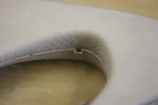
We created a 3D print component representing a wall or ceiling assembly and used laser cut Plexiglas to represent the glass panels that would fill in the voids. The first joint uses L-shaped brackets printed as a part of the mass in combination with matching precut holes on the glass panel which hold the panel in place. The second joint uses the same L-shaped brackets and matching holes except the panel is offset slightly not filling the entire void leaving a small air space. The third joint uses pairs of pockets printed into the 3D structure which allow small metal tubes to slide in and pin the panel in place. The final joint condition uses a lip which the panel fits against in combination with single pockets (and pins) printed into the structure to hold the panels in place.

- Beatty - Holland -

image from www.d-shape.com

Thursday, February 18, 2010

Puzzle Time


Our tool was the laser cutter with chipboard as a material. We experimented with some different sizes but ultimately decided on 1/32". This would allow us much play and flexibility as our whole concept consisted of layering. We decided to modify a puzzle featuring six different pieces. The pieces were based on a 1/4" grid that would take advantage of layering pieces cut by the laser cutter. The width of the pieces was a 1/2" which took 16 layers to make a square piece!


To make my assembly easier, the layers were each labeled from A - F. This not only helped with identifying the pieces, but was critical to putting the final model together. Chipboad was an ideal material for this project. It allowed for tolerances and could adjust in certain circumstances. The pieces are obviously still very precise, and have to be for a successful fit. But, the chipboard has a little give making it less likely for failure.

Our next step was to figure out a way to connect a finished puzzle to another one. As the picture shows, the final piece( labeled A) is the one which allows for movement in and out of the middle joint. This gave us the most opportunity to play with connections. Our solution became a two step process with piece E. Each was given a male and female end. After after the male end of E was connected to the female end of E(from the second puzzle), piece A was intended to slide over that joint locking it in place. The A connection was taking advantage of friction between the layers and the tolerances allowed it to lock into each other, once again using a male and female end.

The idea was to create an infinite puzzle, that could continuously build upon itself.


Wednesday, February 17, 2010

Joint Ornament

Sara Ben Lashihar

Joint Assignment

02/18/2010

The project is based on the idea of mesh timber in furniture industry in Middle East. In that industry, decorative wood panels are linked to each other by joints and glue to create wonderful ornaments.

I used in my project 3D printer by producing two pieces of the proposed joint. And I suggested three types of this joint: pressure, connection, and overlay.


Pressure

Connection

Overlay